免职声明:本网站为公益性网站,部分信息来自网络,如果涉及贵网站的知识产权,请及时反馈,我们承诺第一时间删除!
This website is a public welfare website, part of the information from the Internet, if it involves the intellectual property rights of your website, please timely feedback, we promise to delete the first time.
电话Tel: 19550540085: QQ号: 929496072 or 邮箱Email: Lng@vip.qq.com
摘要:SAR(逐次逼近寄存器)ADC基准电压对转换精度的影响比最初想象的还要大。图1所示为理想和带增益误差的3位ADC转换器的传递方程。ADC的传递方程等于: 在这里,DCODE为数字输出代码,VIN为转换器的输入电压,VOS为转换器偏置电压,VREF为用于转换器的基准电压,N..
|
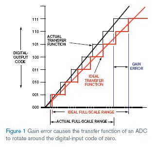
SAR(逐次逼近寄存器)ADC基准电压对转换精度的影响比最初想象的还要大。图1所示为理想和带增益误差的3位ADC转换器的传递方程。ADC的传递方程等于:
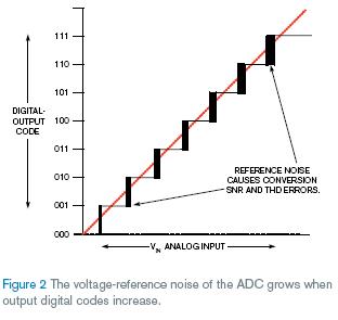
在这里,DCODE为数字输出代码,VIN为转换器的输入电压,VOS为转换器偏置电压,VREF为用于转换器的基准电压,N为ADC位数或ADC分辨率,VGE为ADC增益误差、基准输出电压误差和基准电压噪声的综合。 容易看到基准电压给定值对ADC绝对精度的影响。对高分辨率转换器,基准电压偏置误差通常比ADC偏置误差大,特别在过温度状态。从传递方程也注意到基准电压误差对较高输入电压转换器的结果影响更大。 可以用ratiometric设计减小ADC和基准电压的误差。这需要电路或微处理器校准算法中加入额外设备。记住校准算法需要每个电路的增益和偏置特性。 基准电压的噪声误差是不同的问题。它影响转换的SNR(信噪比)和THD(总谐波失真)。基准电压噪声影响输入电压较高的ADC转换器的SNR和THD(图2)。
如果转换器在基准电压引脚缺少内部缓冲器,将会引入或输出电流尖峰。转换器在转换期间使用这些电流为内 不要尝试用0V或地的输入电压测试ADC。如果希望看到转换中基准电压源的影响,尝试使用直流全范围输入,信号输入将帮助看到系统的频率响应(参看文献1)。 英文原文: ADC voltage-reference errors impact full-scale conversions By Bonnie Baker -- EDN, 11/22/2007 SAR (successive-appoximation-register) analog-to-digital references have more influence on conversion accuracy than you may initially think. Figure 1 shows the transfer function of an ideal 3-bit ADC and the same converter with gain error. The transfer function of an ADC is equal to: where DCODE is the digital-output code, VIN is the input voltage to the converter, VOS is the converter’s offset voltage, VREF is the reference voltage applied to the converter, N is the number of ADC bits or the ADC resolution, and VGE is the combined ADC-gain error, reference-output-voltage error, and reference-voltage noise. It is easy to see how the voltage reference’s specified value affects the ADC’s absolute accuracy. For high-resolution converters, the reference-offset error is usually greater than the ADC-offset error, particularly over temperature. You will also notice from the transfer function that the reference errors have more influence on the converter results with higher input voltages. You can reduce the ADC and reference-source errors with a ratiometric design. This scenario may require additional devices in the circuit or a processor/microcontroller-calibration algorithm. Remember that calibration algorithms require gain and offset characterization for each circuit. The reference’s noise error is a different matter. It affects the SNR (signal-to-noise ratio) and the THD (total harmonic distortion) of a conversion. The reference noise impacts the converter’s SNR and THD at higher ADC input voltages (Figure 2). If the converter lacks an internal buffer at the reference pin, you will notice incoming or outcoming current spikes. The converter uses these currents during the conversion cycle to charge internal capacitors. This knowl Don’t try to test your ADC with an input voltage of 0V or ground. If you hope to see the effects of your voltage-reference source on your conversions, try to use a dc full-scale input and then a signal input that will help you look at the system’s frequency response (Reference 1). Reference Oljaca, Miro and Bill Klein, “Improved Voltage Reference Circuits Maximize Converter Performance,” Texas Instruments Webinar on Demand. |


